Prepping the Westerbeke for startup involved raiding the spares kit to replace some parts. I ordered two replacement oil filters and a fuel filter element from Torresen Marine here in Michigan for nearly $50.00, but I held off buying a replacement impeller because I thought I could find one for less than $40 for the original Westerbeke part.
After a little internet sleuthing, I've found an alternative FRAM number for the Westerbeke oil filter: PH3593A. I have yet to confirm that it's a match, but that number should cross reference with other brands, too, such as Bosch. I don't intend to be cheap, but where a less expensive - and equally suitable - alternative is available, why not use it?
The Westerbeke impeller kit (part #34440) retails for about $40, but the impeller is a Johnson 810 (#09-810B-1) that can be had online for less than $20, including shipping. I just bought one on Ebay for $18.45.
For commonly replaced parts, it seems like a good thing to have alternatives.
Wednesday, July 18, 2012
Good Pressure
I was concerned the other day that I should have been seeing higher oil pressure on the engine panel gauge, especially when I ran the engine up to RPM, so I bought a mechanical gauge with more precise increments and installed it this morning. Turns out I've got good oil pressure.
I saw 40 psi at startup, and 46 psi at RPM. The pressure dropped to 36 at idle after the engine warmed up a bit. The manual indicates that oil pressure will range between 30 and 55 psi during normal operation. At idle, oil pressure will range between 15 and 30 psi, so I think I'm in good shape.
I saw 40 psi at startup, and 46 psi at RPM. The pressure dropped to 36 at idle after the engine warmed up a bit. The manual indicates that oil pressure will range between 30 and 55 psi during normal operation. At idle, oil pressure will range between 15 and 30 psi, so I think I'm in good shape.
Monday, July 16, 2012
A Determination Deferred
I realize this is a bit crazy, but you live and learn.
I bought the A30 nearly six years ago (for a good price) and trusted the seller to represent the details accurately. I knew that the newer Westerbeke diesel had 241 hours on it. I checked the oil, coolant, and ensured that it had been winterized properly. The prop shaft bore a tag indicating that the yard had winterized the engine and put her away, so I wasn't too concerned.
Well, all these years later, after returning to working on her, I decided it was past time to know that I had an operational engine before I invested any more time or money into the project. (Crazy, I know - not that I decided it was time, but that it took so long).
I'd pulled the engine in the fall and had it sitting on a homemade cart in the garage, so I wheeled it toward the garage door and began getting it ready to run. That meant first cleaning off all of the nasty fiberglass dust that had accumulated during my interior demolition phase. After an hour with a toothbrush and the Shop-Vac, it was nicely"detailed" and ready for more important checks, which included inspecting and replacing the raw water impeller (with two cracked vanes), inspecting and installing the primary fuel filter (some idiot had removed the filter element, entirely trusting a fuel/water separator type filter that was plumbed between the tank and the engine), rigging up the coolant recovery tank, and double checking fluid levels in the engine and transmission.
I plumbed the fuel lines into a fresh tank of diesel and the water intake into a bucket of water, wired up the battery and engine control panel, then proceeded to crank the engine with the engine shut-off lever depressed in an attempt to circulate oil through the engine before the thing (hopefully) started, which was the advice I got from a Westerbeke tech. I repeated the cranking a few times until I thought (hoped) there was sufficient oil circulated to minimize the likelihood of damaging the engine on startup.
It was time to give it a go for real. Here's what happened:
I ran the engine up to temp, then shut it down and changed the oil. I started it back up and let it run until it was back up to temp. Everything seemed to check out ok. My only concern is that the oil pressure didn't seem to rise as much as I thought it would/should when I eventually raised the RPM. The manual states that 15-40 psi is the normal range for the engine, but I only saw about 30 psi at RPM. Perhaps I have nothing to worry about, but I ordered a mechanical oil pressure gauge that will allow me to find out if the panel gauge reading is accurate or not.
At any rate, I'm relieved that it looks like it's safe to move on with the project.
Thursday, July 05, 2012
Bilge and cutless bearing
Having a lot of other stuff to do - canvas jobs, prepping Ariel for launch and replacing her leaking diesel tank, spending time with my two boys, and, oh yeah, my full-time job - means not much stuff gets done on the Alberg 30. I did, however, spend a couple hours doing what I seem to do best: take things apart (let's hope I can manage to get those things back together eventually).
I mixed up some epoxy and applied a thin coating over the exposed material in the keel as an initial seal. Once it was tacky, I mixed up epoxy thickened with colloidal silica and used it to fill in some of the larger gaps. Atop that I laid a layer of fiberglass cloth. Although that provided some measure of protection to that area, it left an irregularly shaped bilge, so I cut a couple pieces of blue DOW styrofoam board to fit and fill the bottom of the bilge, creating a flat surface that sloped slightly forward from the aft portion of the bilge. Eventually that foam board will receive a layer of 1708 biaxial cloth that will become the new bilge bottom, sealing the area beneath.
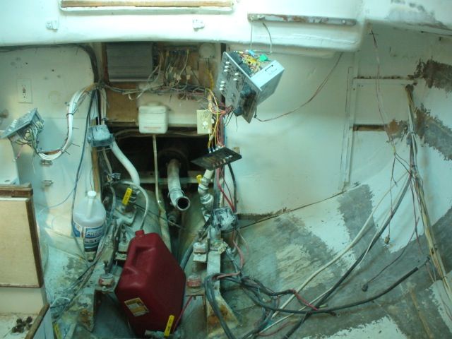
There were a couple tasks that I wanted to get done: 1) clean out the bilge and seal the exposed cement (or whatever it is) that fills the area at the aft end of the bilge; 2) remove the ridiculous web of wiring and the offensive Celebrity ski boat electrical panel; 3) remove the old engine mounts in preparation for new engine beds.
Here you can see the DC panel with stereo and a dangling cheap-o accessory panel hanging to port, and the AC panel to starboard. At the center are several blocks of wood (secured with a dozen or more screws through the cockpit footwell) to which are fastened an amp for the stereo and a buss or two.
I began by stripping all the bits and pieces of wiring out of the boat. Most of the wiring is newer, so I did what I could to preserve lengths of wire that I might be able to reuse. I am amazed that the PO thought it was necessary to have five separate AC outlets located within such a small cabin. Ariel, our CD36, has three AC outlets, and never have we wanted for more. Of course, the number of outlets in the A30 should come as no surprise given all the other "improvements."
With all the wiring stripped out of the boat and organized, I cleaned up the area and vacuumed out the bilge. In the area just forward of the aftermost floor, there was a piece of exposed ballast and aft of it a cement-like material intended, I suppose, to keep the ballast in place and the fill the aft area of the keel.
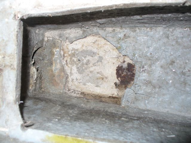 |
| The rusted area of exposed ballast is visible at right. |
Water had apparently leaked through this area for some time because a previous owner installed a drain in the bottom of the keel just aft of this position. Once I'd vacuumed the junk out of the bilge, I noticed a hole had been drilled down through the cement, and after rodding it out with a screw driver I was able to see through to the drain in the keel. I'm not too keen on having a exposed fitting mounted to the bottom of the keel where it could be damaged or ripped loose in a grounding, so I will eventually remove it and install a garboard drain even with the bilge bottom.
 |
| After portion of the bilge showing the exposed material. |
I mixed up some epoxy and applied a thin coating over the exposed material in the keel as an initial seal. Once it was tacky, I mixed up epoxy thickened with colloidal silica and used it to fill in some of the larger gaps. Atop that I laid a layer of fiberglass cloth. Although that provided some measure of protection to that area, it left an irregularly shaped bilge, so I cut a couple pieces of blue DOW styrofoam board to fit and fill the bottom of the bilge, creating a flat surface that sloped slightly forward from the aft portion of the bilge. Eventually that foam board will receive a layer of 1708 biaxial cloth that will become the new bilge bottom, sealing the area beneath.
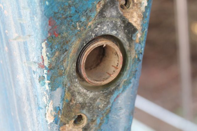
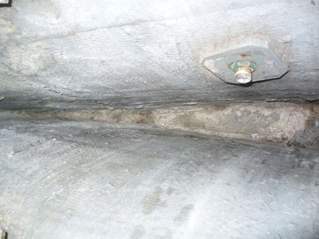
It was too hot to continue work in the boat, so I turned my attention to removing the old, worn cutless bearing as part of prepping for reinstalling the engine. The cutless bearing housing screws onto the molded-in stern tube. Removal requires removing the two bolts that are threaded into the keel deadwood, then unscrewing the cutless bearing housing. Unfortunately, it appears that I may have partially "unscrewed" the stern tube as I was attempting to remove the housing.
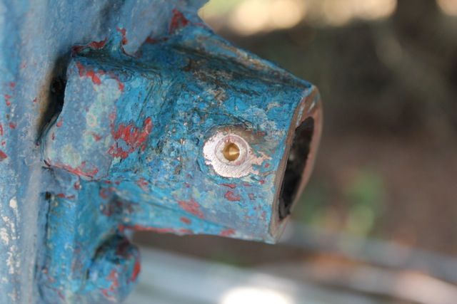
The two bolts that secure the housing are visible in the photo to the left. The aftermost portion of the housing also shows the cutless bearing sleeve pressed into the housing. In this case, it is also evident that a previous owner got a little carried away with a grinder or reciprocating saw and cut the housing and the bearing - presumably because the bearing stood proud of the housing. Why they didn't just cut the bearing flush without damaging the housing is a mystery.
Two set screws on either side of the housing are used to lock the cutless bearing in place. I was able to remove the starboard screw easily, but the port screw crumbled when I tried to turn it.
While I was operating under the delusion of removing the cutless bearing with the housing still attached to the boat, I decided to drill out the set screw - visible at left. Even with both set screws removed, there was no easy way to remove the cutless bearing. I even tried cutting some reliefs in the bearing sleeve, but there was no way to pry it loose without damaging the housing further.
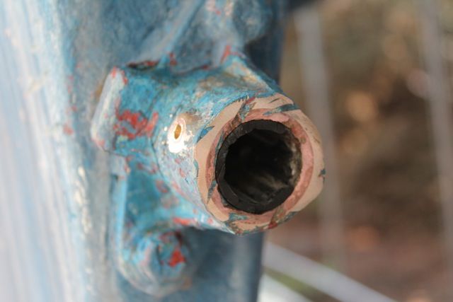
The threaded portion of the stern tube that attaches to the bearing housing is visible where a portion of the rubber bearing has been removed.
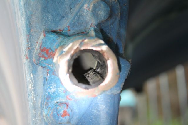
And here is the threaded stern tube with the bearing housing removed. Since I fear the stern tube "unscrewed" partially during removal of the housing, the next step is to remove the stern tube and prepare it and the housing, with a new cutless bearing, for reinstallation in a bed of sealant. The important bit is to ensure that all of these bits line up well with the new engine mounts, etc. That process is something I've only read about, so I'll be feeling my way along - carefully.
Timing for all of this has worked out quite well since Jimmy of SV Cookie is working through some of the same issues. I've already sought his input on some of this and appreciate his contributions.
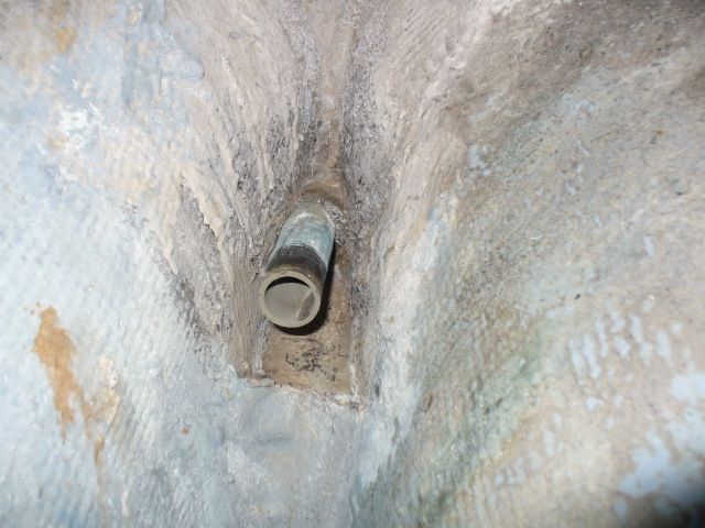 |
| The stern tube |
Timing for all of this has worked out quite well since Jimmy of SV Cookie is working through some of the same issues. I've already sought his input on some of this and appreciate his contributions.
Subscribe to:
Posts (Atom)