Tuesday, July 16, 2013

Bulkhead Templates

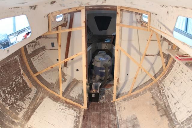
This is a milestone for me - and for the project. I've actually begun reconstruction.

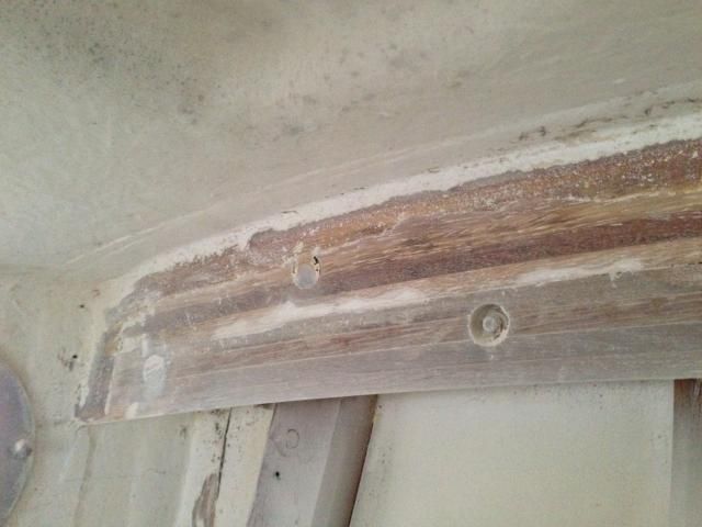
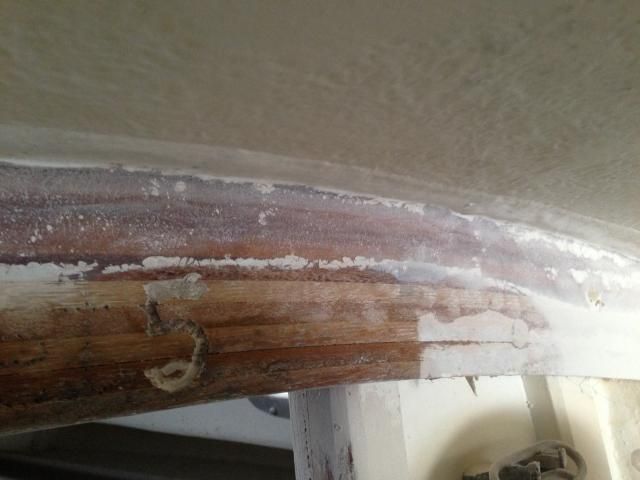
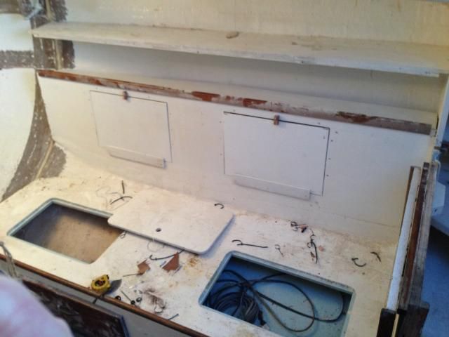
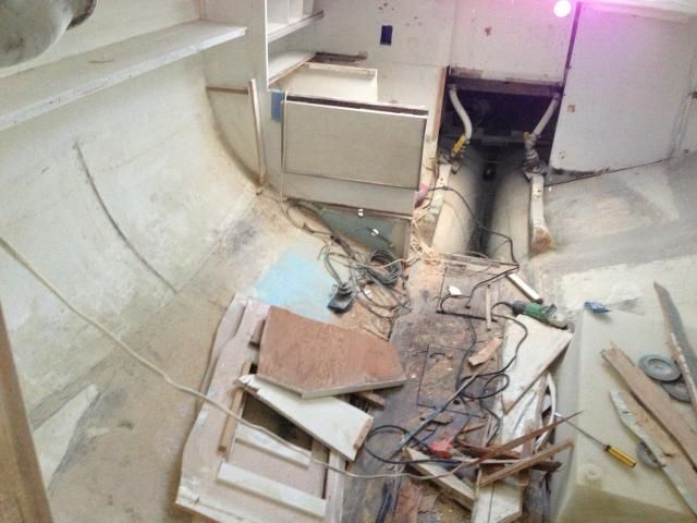
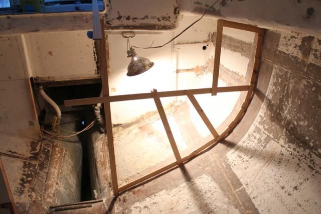
I created templates for the bulkheads that will define the head and hanging locker, and the galley/ice box area. These templates will be transferred to plywood, which will then be cut and fitted into place. It's exciting to see the interior beginning to take shape. Next step is to purchase the plywood - pricey!

Galley bulkhead template.

Head (port) and hanging locker templates.


Friday, July 12, 2013

Studs and Glass

I've been acquiring bits and pieces to take care of a few small issues before I can begin more major items like installing the stern tube and engine beds.

A couple of the engine mount studs were bent, so the other day I removed them and took one to a local store to match with threaded rod. Turns out I bought the wrong size - Standard instead of metric. I figured it out AFTER cutting four new studs.

No one local had the M12 1.75 threaded rod, so I ordered it and the nuts from McMaster-Carr. They ship out of their Chicago warehouse, so I had the pieces the next day.

I cut the new studs, cleaned up the ends, and threaded them into the mounts and locked them in place. I positioned all four studs evenly in their mounts and placed the lower stop nuts at 2-3/8" to establish a level position for the engine, leaving plenty of room to adjust the engine up or down as necessary later. One bit that's somewhat puzzling is that the engine mount flange dimensions/specs don't match the Westerbeke schematic. I planned to make a template of the engine based on the Westerbeke schematic, but it doesn't match the measurements I'm getting from the actual engine. It appears that the port forward isolator mount/flange is not the one indicated in the schematic. Whether or not it's original Westerbeke, I don't know, but the front mounts are a bit farther apart than indicated on the drawing.


In the process of doing all that, I was once again reminded of how careless a PO (or a professional) had been: one of the studs was not even the right size and wiggled in the engine mount.


The other task I completed was fiberglassing the bottom of the bilge under the engine. Months ago I had scraped and vacuumed out broken pieces of resin and cement that were part of Whitby's construction method for filling the lower portions of the bilge and preventing the ballast from moving aft (I suppose). I used blue sheathing foam cut to shape to bring the area above the cement even with the rest of the bilge. In fact, I actually sloped it forward a bit to prevent water from collecting at the very aft end of the bilge, where a pump wouldn't be able to get it out.


With that done, I wiped down the area with acetone - I'd already sanded it - and put in a 6" wide strip of biaxial cloth. The cloth wasn't wide enough at the forward end to come up the hull side more than a 1/2", so I cut three more lengths of cloth and placed them laterally across the bilge floor and well onto the sides of the hull.

With the bilge fiberglassed, I don't have to worry about any water soaking into the cement and any voids down there. Additionally, I can now install a garboard drain and use it periodically to rinse the interior of the hull after sanding. The best part of having it done is that I can now begin work on the engine beds and stern tube.

Monday, April 08, 2013

Instruments

Tradewinds came to me with Standard Horizon digital depth and speed, but the the speed transducer doesn't seem to be working and the depth transducer is MIA (although it could be stored with other A30 parts and I've just forgotten; at any rate, it's not installed).

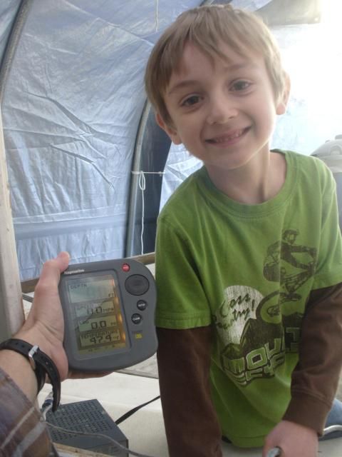
Even though reinstalling instruments is way, way down the line, I was thinking about what to do. I wasn't a big fan of the Raymarine fishfinder that someone installed on a super classy dashboard mount that used to jut from the cabin trunk, but I dug out the manual (thank goodness for a previous owner who kept everything) and discovered that it actually has some decent functions AND it can be flush mounted. Cool. I cleaned it up and took it out to the boat to see if it worked.

My younger son, always eager to help.

It does! And it's actually pretty cool. I don't like the fish finder screen much, but this data screen is perfect for sailing, showing depth, speed, log, and water temp. My eldest son (not pictured) spun the paddlewheel while I watched the screen for a reading. Amazingly, we hit nearly 6 kts in the driveway. So, it looks like this unit will be flush mounted on the rear of the cabin trunk when the time comes to put things back together. This little unit will save over $300, the cost of a relatively inexpensive Raymarine ST40 Bidata.

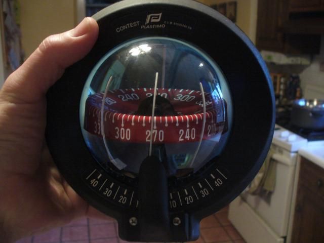
While I was feeling handy and seeing what I could do to make "old" instruments serviceable, I brought the compass in and cleaned it up. A large bubble had formed in the globe, and I just happened to have some Ritchie compass fluid on hand from servicing Ariel's compass a few years ago, so I took the thing apart, improvised a filler using a turkey syringe and part of a foam earplug, and refilled the fluid.


It worked! And the two lights work as well.

I also finished what I hope will be the final round of major sanding/grinding. Using a combination of angle grinder w/ flapper wheel and a 6" sander, I think I'm ready to call that part of the project DONE!


Sunday, April 07, 2013

Some Sanding and Stripping Parts

Things are moving right along now that I've been spending an hour here and there working on the boat. Previously, I felt that unless I was willing to do marathon-length efforts, it wasn't worth getting geared up. For new readers, this is what "geared up" looks like: full-face respirator, Tyvek suit, leather gloves, tape at the neck and wrists, and a 4-1/2" angle grinder.

To borrow wisdom from Tim Lackey, keeping things going - even if they're only small things - is important and actually accomplishes quite a bit over time. Sanding does seem to go on forever, however, but really it's not too bad.


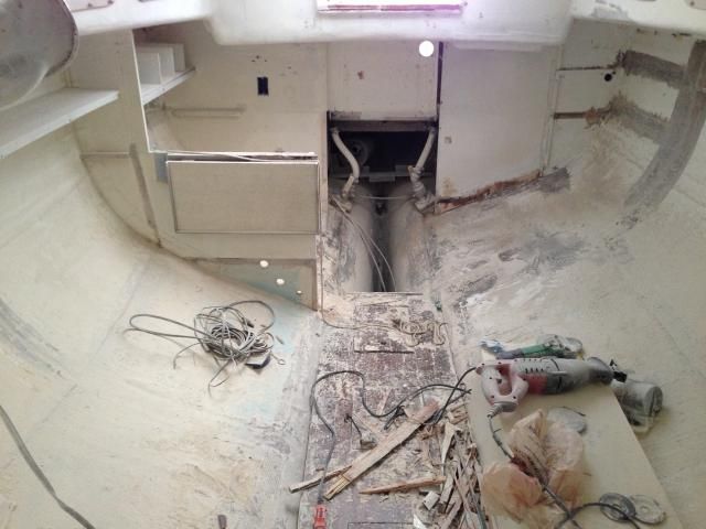
I'm eager to get things ready for reconstruction. To that end, I used a 6" sander with 40 grit paper to knock off loose paint in the saloon, then switched to a 4" sander with 80 grit to do the overhead. It's tough to know just how much paint must be removed from the hull, but I think I'm just about there. Probably one more round of sanding should do it.


There are a few spots where the interior of the overhead is especially uneven. Those areas will need a little epoxy filler before painting. Such is the nature of an early 60s fiberglass sailboat.

I gave the interior a general cleaning when I finished sanding. I'm amazed at just how much dust I've generated. Sweeping down the hull sides produced several pounds of fine dust that looked like flour.

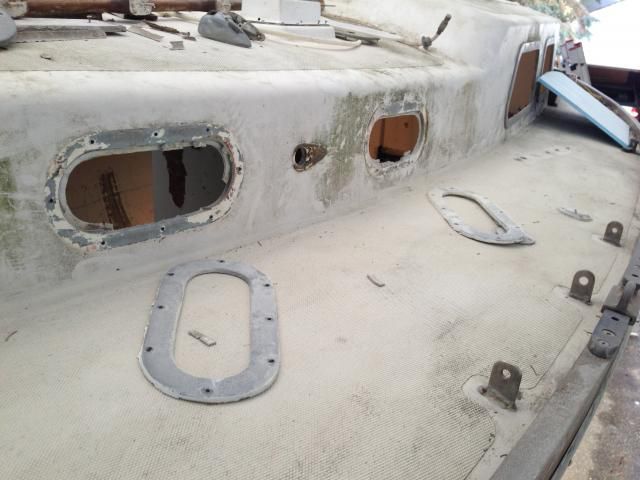
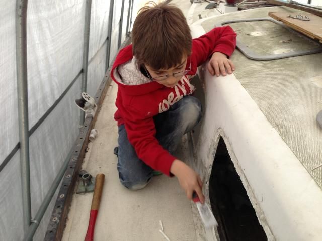
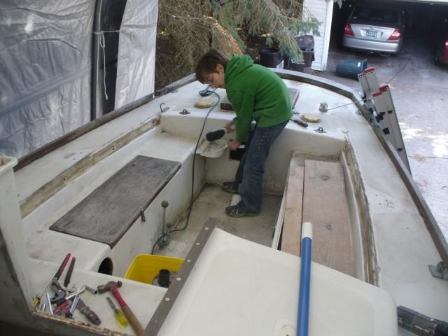
With the help of my son, I pulled the ports and frames, then cleaned the openings. Jake's a good little helper, and he scraped the old sealant from around the openings.


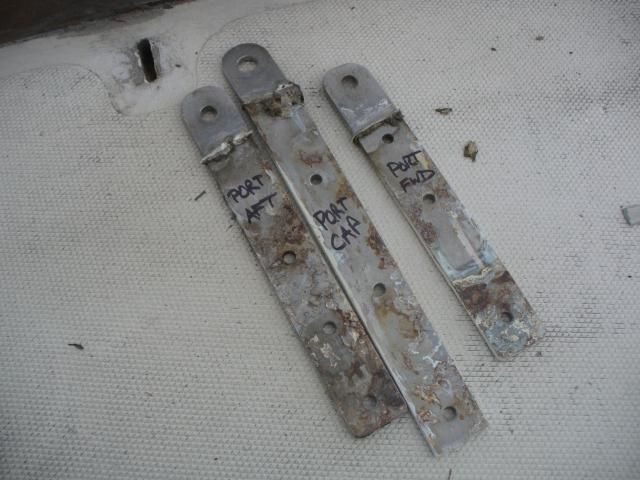
We pulled the chainplates as well. I'm not sure whether they're original or not, but they have not been upgraded, per the Alberg 30 site, to 5/16" shoulder bolts. The chainplate bolts are a known weak spot on these boats, so I'm surprised no one made the change in all these years. It was interesting to discover that although there were three fasteners on the port forward chainplate, there were only two holes in its partner on the starboard side. Odd. All of the chainplates will be cleaned up and the fastener holes enlarged before going back in with new 5/16" should bolts and backing plates.


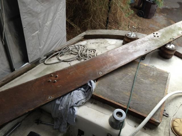
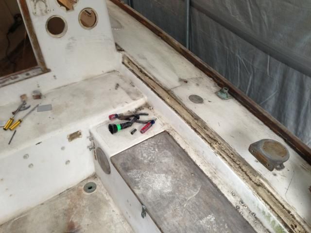
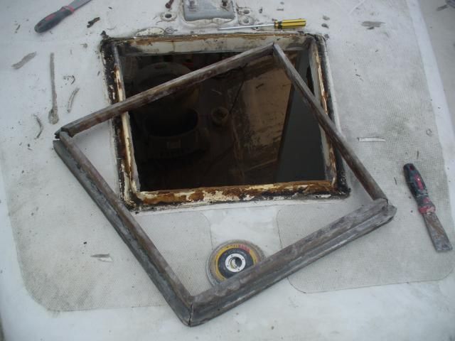
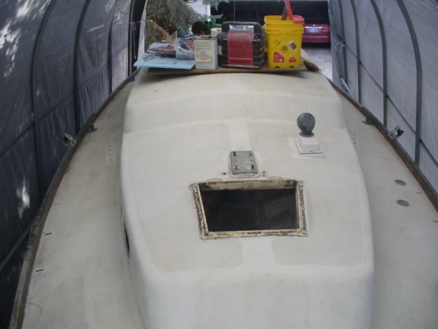
I've also removed the coamings, forward hatch and surround, and a few other odds and ends that would eventually have had to come off for deck refinishing.


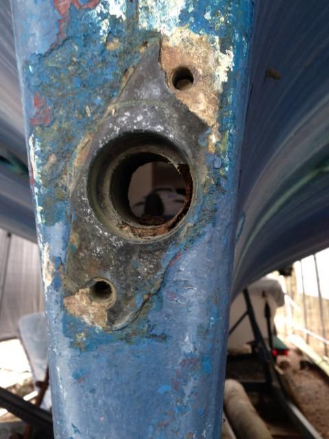
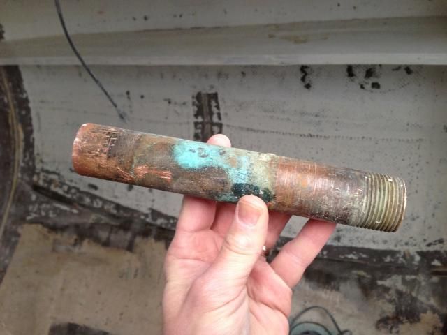
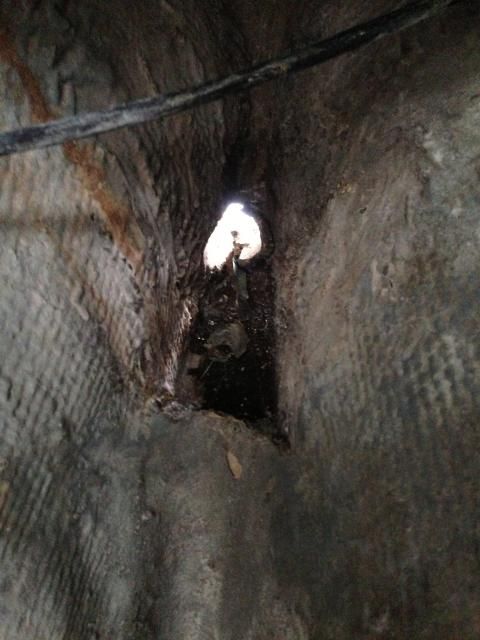
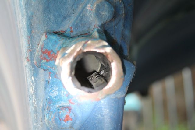
I was pleased to discover that the original bronze stern tube was fairly easy to remove. I used a pipe wrench from inside the boat to unscrew the threaded aft end through the thickened epoxy Whitby used during construction. I then used a chisel to clear the old epoxy from the inside of the hole. It's clean and ready for the next step of using a new fiberglass stern tube when it comes time to install the engine and determine alignment.


Jake and I cleaned up before calling it a day. Jake did a fantastic job of sweeping and sprucing things up - and, in his own words, he had "the best day" helping his daddy.
 

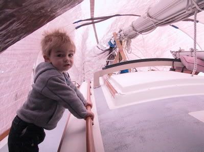
And here Jake is a few years ago helping me aboard our Cape Dory 36. Time sure does fly!


Sunday, March 31, 2013

Delaminated Tabbing & More Grinding

Grinding seems to go on and on. I cut out the remaining galley bulkhead then used my angle grinder with flapper wheel to smooth and grind tabbing remnants throughout the cabin. Nothing too fun about that. Dust, dust, and more dust.


I also removed the original engine beds and ground the tabbing smooth in that area.


While poking around in the cabin, I noticed that some of the original tabbing on the main bulkheads that support the mast beam seemed to have delaminated a bit. I really wasn't sure just how extensive the issue was, but I decided that it was best to continue the mess and finish all the grinding in one mega-round than to have to keep making dusty messes. I ground the tabbing in several suspect areas, and in some cases had to grind it completely down to the bulkhead because it was dry and delaminated.


Once all the surfaces are prepped, I'll add new tabbing to secure the joint.

Friday, March 22, 2013

More Destruction

I seem to be good at demolition. Let's hope I can manage some reconstruction at some point.

After making some decisions about water tankage and placement, I decided to go ahead and remove the starboard settee - the port settee had already been removed by a previous owner - in order to have port and starboard settees match each other. With the water tank I have on hand for the port settee, the new berth will have to sit higher than the original, so I figured I may as well double the capacity (from 18 gallons to 36) by adding a matching water tank under the starboard settee.

I hate to make more of a mess, but rebuilding the starboard settee as well has a couple benefits beyond matching the port side: 1) I won't have to scarf new material to the existing stubs of door jamb; 2) I won't have unnecessary holes from old equipment and hoses to contend with or repair; 3) I can do a better job of making the access hatches in the backrest of the settee than a PO had done; 4) starting from scratch will make installation of the forward bulkhead easier.

Here's the starboard settee before destruction:

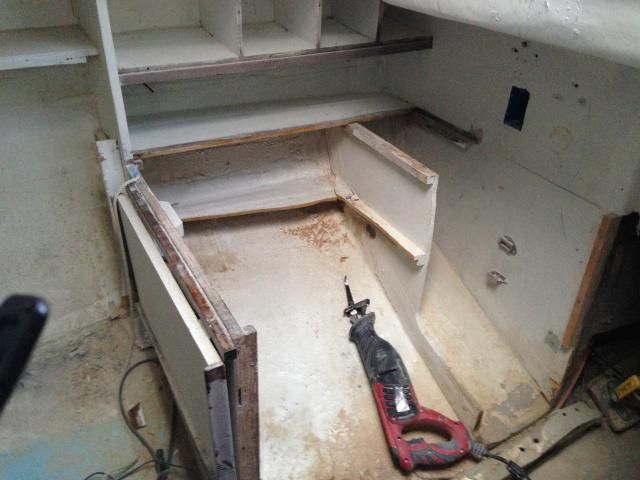
I used a Sawzall for the first time on this project, and it made the work go much faster. Previously, I've used an angle grinder and cutoff wheel to cut the fiberglass tabbing. The Sawzall worked a hundred times better than the cutoff wheel, and it creates much less mess.

Settee gone!

I started working on removing shelving and a bulkhead in the area of the galley, but my Sawzall blade was just too dull. I'll be leaving the main galley bulkhead in place, but I'll remove the shelf, small bulkhead, and the galley-top remnant visible in the picture.

A PO carved out the intermediate bulkhead, so I'll remove it completely.


Wednesday, July 18, 2012

Alternate Part Numbers and Sources

Prepping the Westerbeke for startup involved raiding the spares kit to replace some parts.  I ordered two replacement oil filters and a fuel filter element from Torresen Marine here in Michigan for nearly $50.00, but I held off buying a replacement impeller because I thought I could find one for less than $40 for the original Westerbeke part.

After a little internet sleuthing, I've found an alternative FRAM number for the Westerbeke oil filter: PH3593A.  I have yet to confirm that it's a match, but that number should cross reference with other brands, too, such as Bosch.  I don't intend to be cheap, but where a less expensive - and equally suitable - alternative is available, why not use it?

The Westerbeke impeller kit (part #34440) retails for about $40, but the impeller is a Johnson 810 (#09-810B-1) that can be had online for less than $20, including shipping.  I just bought one on Ebay for $18.45.

For commonly replaced parts, it seems like a good thing to have alternatives.

Good Pressure

I was concerned the other day that I should have been seeing higher oil pressure on the engine panel gauge, especially when I ran the engine up to RPM, so I bought a mechanical gauge with more precise increments and installed it this morning.  Turns out I've got good oil pressure.

I saw 40 psi at startup, and 46 psi at RPM.  The pressure dropped to 36 at idle after the engine warmed up a bit.  The manual indicates that oil pressure will range between 30 and 55 psi during normal operation.  At idle, oil pressure will range between 15 and 30 psi, so I think I'm in good shape.

Monday, July 16, 2012

A Determination Deferred

I realize this is a bit crazy, but you live and learn.

I bought the A30 nearly six years ago (for a good price) and trusted the seller to represent the details accurately.  I knew that the newer Westerbeke diesel had 241 hours on it.  I checked the oil, coolant, and ensured that it had been winterized properly.  The prop shaft bore a tag indicating that the yard had winterized the engine and put her away, so I wasn't too concerned.

Well, all these years later, after returning to working on her, I decided it was past time to know that I had an operational engine before I invested any more time or money into the project.  (Crazy, I know - not that I decided it was time, but that it took so long).

I'd pulled the engine in the fall and had it sitting on a homemade cart in the garage, so I wheeled it toward the garage door and began getting it ready to run.  That meant first cleaning off all of the nasty fiberglass dust that had accumulated during my interior demolition phase.  After an hour with a toothbrush and the Shop-Vac, it was nicely"detailed" and ready for more important checks, which included inspecting and replacing the raw water impeller (with two cracked vanes), inspecting and installing the primary fuel filter (some idiot had removed the filter element, entirely trusting a fuel/water separator type filter that was plumbed between the tank and the engine), rigging up the coolant recovery tank, and double checking fluid levels in the engine and transmission.

I plumbed the fuel lines into a fresh tank of diesel and the water intake into a bucket of water, wired up the battery and engine control panel, then proceeded to crank the engine with the engine shut-off lever depressed in an attempt to circulate oil through the engine before the thing (hopefully) started, which was the advice I got from a Westerbeke tech.  I repeated the cranking a few times until I thought (hoped) there was sufficient oil circulated to minimize the likelihood of damaging the engine on startup.

It was time to give it a go for real.  Here's what happened:


I ran the engine up to temp, then shut it down and changed the oil.  I started it back up and let it run until it was back up to temp.  Everything seemed to check out ok.  My only concern is that the oil pressure didn't seem to rise as much as I thought it would/should when I eventually raised the RPM.  The manual states that 15-40 psi is the normal range for the engine, but I only saw about 30 psi at RPM.  Perhaps I have nothing to worry about, but I ordered a mechanical oil pressure gauge that will allow me to find out if the panel gauge reading is accurate or not.

At any rate, I'm relieved that it looks like it's safe to move on with the project.

Thursday, July 05, 2012

Bilge and cutless bearing

Having a lot of other stuff to do - canvas jobs, prepping Ariel for launch and replacing her leaking diesel tank, spending time with my two boys, and, oh yeah, my full-time job - means not much stuff gets done on the Alberg 30.  I did, however, spend a couple hours doing what I seem to do best: take things apart (let's hope I can manage to get those things back together eventually).

There were a couple tasks that I wanted to get done: 1) clean out the bilge and seal the exposed cement (or whatever it is) that fills the area at the aft end of the bilge; 2) remove the ridiculous web of wiring and the offensive Celebrity ski boat electrical panel; 3) remove the old engine mounts in preparation for new engine beds.

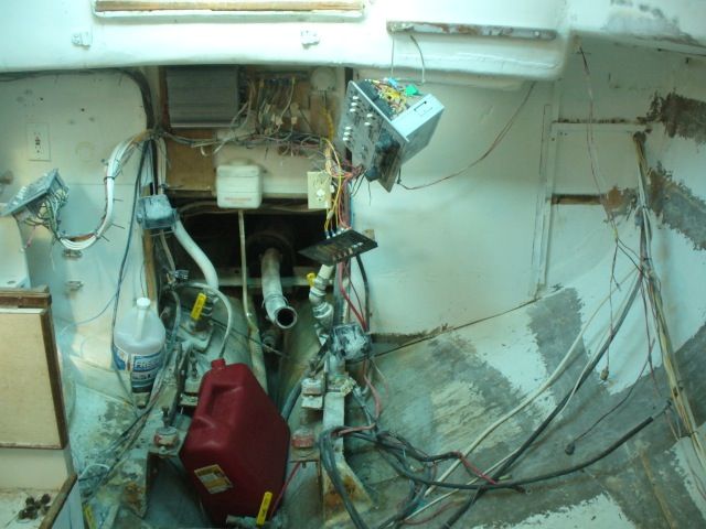
Here you can see the DC panel with stereo and a dangling cheap-o accessory panel hanging to port, and the AC panel to starboard.  At the center are several blocks of wood (secured with a dozen or more screws through the cockpit footwell) to which are fastened an amp for the stereo and a buss or two.

I began by stripping all the bits and pieces of wiring out of the boat.  Most of the wiring is newer, so I did what I could to preserve lengths of wire that I might be able to reuse.  I am amazed that the PO thought it was necessary to have five separate AC outlets located within such a small cabin.  Ariel, our CD36, has three AC outlets, and never have we wanted for more.  Of course, the number of outlets in the A30 should come as no surprise given all the other "improvements."

With all the wiring stripped out of the boat and organized, I cleaned up the area and vacuumed out the bilge.  In the area just forward of the aftermost floor, there was a piece of exposed ballast and aft of it a cement-like material intended, I suppose, to keep the ballast in place and the fill the aft area of the keel.
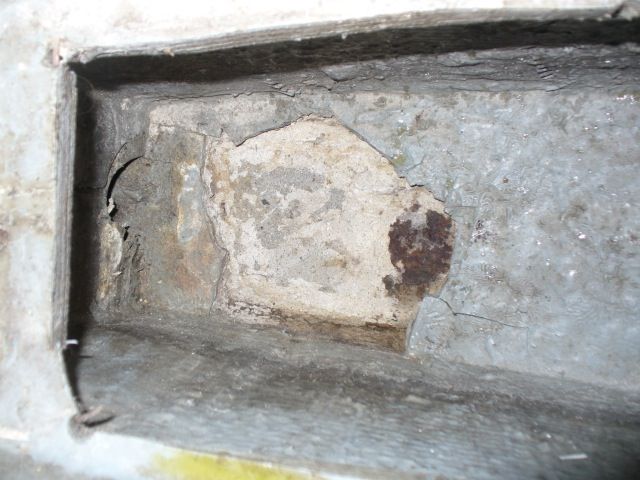
The rusted area of exposed ballast is visible at right.
Water had apparently leaked through this area for some time because a previous owner installed a drain in the bottom of the keel just aft of this position.  Once I'd vacuumed the junk out of the bilge, I noticed a hole had been drilled down through the cement, and after rodding it out with a screw driver I was able to see through to the drain in the keel.  I'm not too keen on having a exposed fitting mounted to the bottom of the keel where it could be damaged or ripped loose in a grounding, so I will eventually remove it and install a garboard drain even with the bilge bottom.
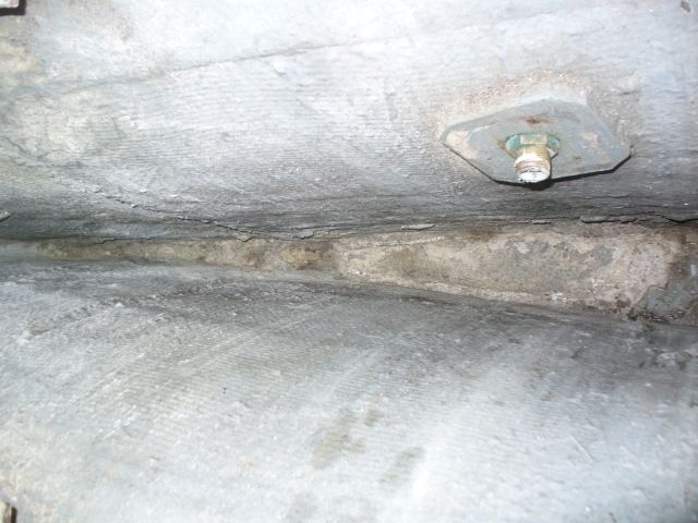


After portion of the bilge showing the exposed material.


I mixed up some epoxy and applied a thin coating over the exposed material in the keel as an initial seal.  Once it was tacky, I mixed up epoxy thickened with colloidal silica and used it to fill in some of the larger gaps.  Atop that I laid a layer of fiberglass cloth.  Although that provided some measure of protection to that area, it left an irregularly shaped bilge, so I cut a couple pieces of blue DOW styrofoam board to fit and fill the bottom of the bilge, creating a flat surface that sloped slightly forward from the aft portion of the bilge.  Eventually that foam board will receive a layer of 1708 biaxial cloth that will become the new bilge bottom, sealing the area beneath.

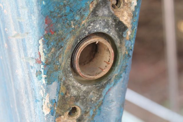
It was too hot to continue work in the boat, so I turned my attention to removing the old, worn cutless bearing as part of prepping for reinstalling the engine.  The cutless bearing housing screws onto the molded-in stern tube.  Removal requires removing the two bolts that are threaded into the keel deadwood, then unscrewing the cutless bearing housing.  Unfortunately, it appears that I may have partially "unscrewed" the stern tube as I was attempting to remove the housing.

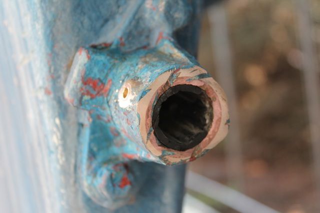
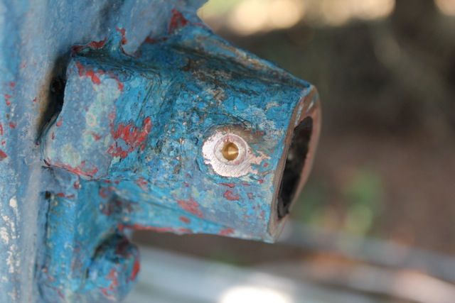
The two bolts that secure the housing are visible in the photo to the left.  The aftermost portion of the housing also shows the cutless bearing sleeve pressed into the housing.  In this case, it is also evident that a previous owner got a little carried away with a grinder or reciprocating saw and cut the housing and the bearing - presumably because the bearing stood proud of the housing.  Why they didn't just cut the bearing flush without damaging the housing is a mystery.

Two set screws on either side of the housing are used to lock the cutless bearing in place.  I was able to remove the starboard screw easily, but the port screw crumbled when I tried to turn it.

While I was operating under the delusion of removing the cutless bearing with the housing still attached to the boat, I decided to drill out the set screw - visible at left.  Even with both set screws removed, there was no easy way to remove the cutless bearing.  I even tried cutting some reliefs in the bearing sleeve, but there was no way to pry it loose without damaging the housing further.

The threaded portion of the stern tube that attaches to the bearing housing is visible where a portion of the rubber bearing has been removed.
And here is the threaded stern tube with the bearing housing removed.  Since I fear the stern tube "unscrewed" partially during removal of the housing, the next step is to remove the stern tube and prepare it and the housing, with a new cutless bearing, for reinstallation in a bed of sealant.  The important bit is to ensure that all of these bits line up well with the new engine mounts, etc.  That process is something I've only read about, so I'll be feeling my way along - carefully.
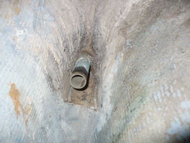


The stern tube


Timing for all of this has worked out quite well since Jimmy of SV Cookie is working through some of the same issues.  I've already sought his input on some of this and appreciate his contributions.
Thursday, November 24, 2011

Removing the engine

Several weeks ago I made the decision to remove the engine so, as I had time, I began removing bits and pieces here and there in preparation. I began with the shaft coupling bolts, expecting them to be not just difficult to reach but firmly stuck. It turns out they were barely tight, and although a tad difficult to reach, they came out easily.

I also figured that the prop would be tough to get off the shaft, so I started drenching it in PB Blaster. I also removed the castle nut and about a 1/2" stack of clear plastic shims that had been cut out of sour cream containers (or something similar) to fill the gap between the aft end of the prop hub and the castle nut. A slipshod installation, to be sure.

I whacked the prop with a piece of wood a few days later, and it slid right off the shaft. It was clear that it was a poor fit: the key didn't fit tightly in the slot and had slightly rounded the edges of the keyway. That'll have to be taken care of upon reassembly.

With all the connections to the engine removed, the engine was ready to come out. My cousin has moved to the area for college, so he gave me a hand with that today. We rigged up a 2x4 with some chain and a come-along above the companionway and lifted the engine clear of its mounts, setting it on the cabin floor. From there it was, of course, up to the bridge deck and then over the side. I reinforced the boat shed bows and used them as lifting points for the come-along. Once over the side, the engine was lowered into a wheel barrow and deposited in the garage. Ryan was kind enough to take a few photos of the process - at least part of it.

PhotobucketPhotobucket
Photobucket

Sunday, November 20, 2011

Getting things moving

I went to the local Family Farm and Home and picked up four 5"x8' red pine fence posts to use as rollers for the boat. I needed to move it forward a bit to get it under the new boat shed. It worked like a charm. Here are a few pics.

Photobucket
Here's how far it was sticking out of the shed.

Photobucket
Placing the posts with a 4-ton floor jack.


Photobucket
All of the posts placed and the boat resting on them.


Photobucket
My trusty old Land Cruiser acting as the anchor. Using a tow strap and a come-along to move the boat.


Photobucket
Almost there.


Photobucket
Tucked inside.

In all only 5' or so of moving forward. It would have been easy to keep on going, though. The transition from asphalt to gravel drive did require some plywood bases to aid the rolling, but otherwise it was a cinch.

Now to get the cover on.